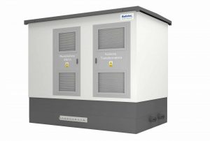
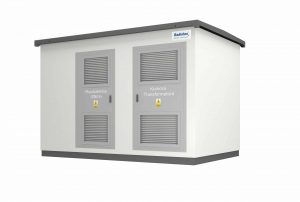
The RDX-W transformer station with an internal service corridor is a solution used in the power grid by energy distributors (generation, distribution, Smart Grid, etc.), end users (infrastructure, industry, developers) and in the renewable energy industry (wind farms, photovoltaic plants). .
The housing's characteristic feature is a fixed width of 2,550 mm or 2,960 mm and the ability to adjust the length from 3,000 mm to 8,000 mm in 200 mm increments.
The complete solution consists of three elements: a tight monolithic cable basement, a body and a roof. The height inside the body is 2450 mm. The oil pans of transformer compartments can accommodate 100% of the oil content from the transformers.
It is possible to design almost any variant of the station.
A typical RDX-W type transformer station consists of a MV and LV switchgear room and a transformer chamber. Additionally, the switchgear room can be separated for several station users, allowing access only to authorized persons. The devices are arranged taking into account optimal technical and economic solutions. Cooling of the devices and ventilation of the station rooms is possible thanks to ventilation grilles located in the doors and walls of the station. If necessary, it is possible to install additional fans in the doors or roof of the station.
In order to adapt the appearance of the station to architectural requirements, it is possible to make overlays in the form of gable or hipped roofs covered with metal roof tiles or ceramic roof tiles.
EXAMPLE ELECTRICAL DIAGRAM OF AN INDOOR SERVICE TRANSFORMER STATION WITH ONE TRANSFORMER
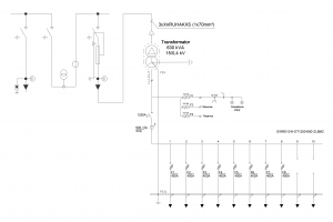
DRAWING OF AN INDOOR SERVICE TRANSFORMER STATION WITH ONE TRANSFORMER
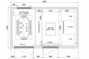
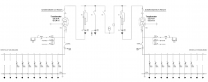
EXAMPLE ELECTRICAL DIAGRAM OF AN INDOOR SERVICE TRANSFORMER STATION WITH TWO TRANSFORMERS
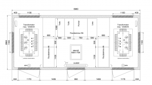
DRAWING OF A TRANSFORMER STATION WITH TWO TRANSFORMERS


 en
en  PL
PL  DE
DE  LT
LT  SV
SV  FR
FR  ES
ES  HU
HU  NO
NO  DK
DK  FI
FI  RU
RU 
